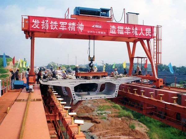
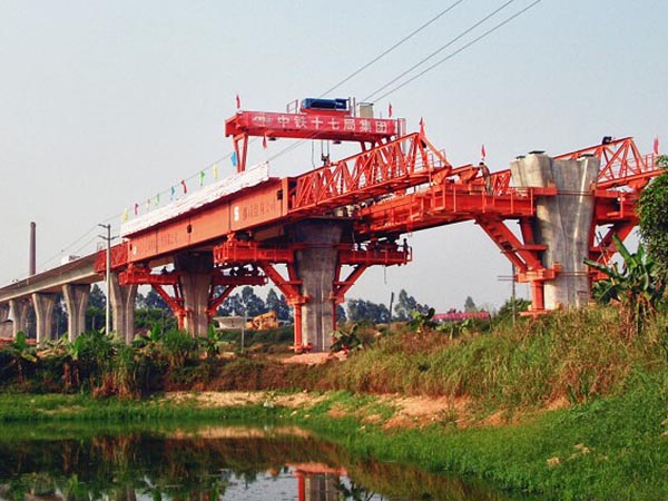
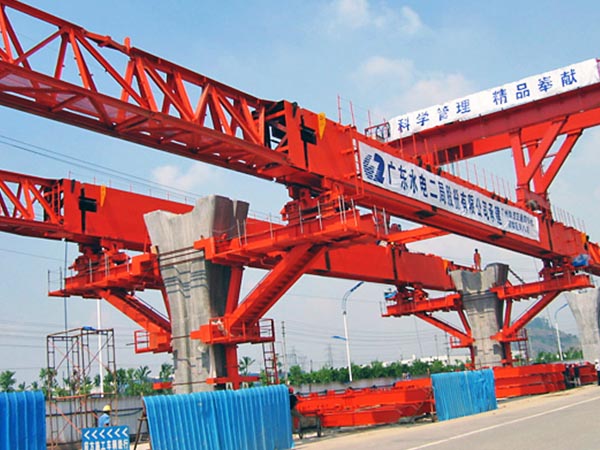
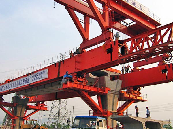
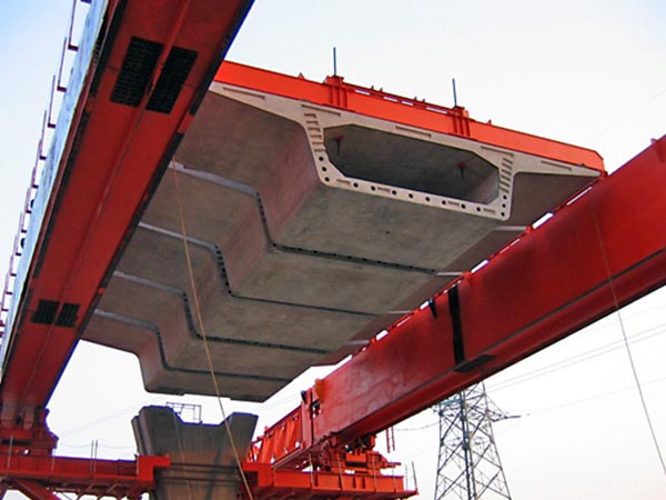
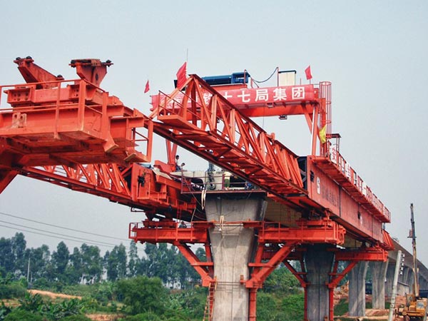
Underslung Segmental Launching Gantry
According to the design and site construction requirements, there are some differences between overhead and underslung segmental launching gantry, such as the design of main girder structure, segment girder hanging mode, each supporting leg structure and launching mode etc.
Whenever Segmental Launching Gantry is use, efficiency is crucial. Huada Heavy Industry Launching Gantries are designed to save every single minute in the construction sequence. Motorized mechanisms are used for continuous self-launching, electric winches with motorized travelling wagons are used for segment lifting and transporting, Spreader Beam with 360° on plane rotating, vertical tilting and angle adjustment functions are provided.
Main features
Underslung LG Innovations of Huada Heavy Industry:
◆Independent main structures, only connected by the gantry crane, allowing transverse adjustment from single to double and even to triple track.
◆Implementation of hinges on our underslung LG has made it possible to erect spans with a horizontal radius down to 75m.
◆The underslung hydraulic adjustment system permits the whole span to be adjusted in all directions to correct possible misalignments during erection.
◆Underslung LG consist of independent self-supporting main structures combined with advanced lifting equipment, creating an exceptionally flexible system for both the balanced cantilever and the span-by-span method.
THE METHOD AND STEPS OF INSTALLATION
The Launching Gantry (Launching Crane) is the heavy duty hoisting equipment which requires very high safety. A little negligence maybe causes serious accident, therefore, the installation of Launching Gantry must be directed or installed by professional works, and the steps are following:
◆ Surveying positioning
◆ Paving rails
◆ Assemble two sides main girder symmetrically.
◆ Installing front and rear connecting frame
◆ Installing front, middle and rear legs
◆ Installing lifting trolley and auxiliary trolley
◆ Hydraulic system, electrical system, operating platform and plug in power
◆ Test run and commissioning.
Type Selection Requirements
Type selection design needs to provide the bridge design drawings and other technical requirements of Client, including bottom bridge structure, upper girder design and site working environment, the main technique parameters needed to be clear:
1. Maximum segment beam lifting weight
2. Maximum suspension weight
3. Bridge span
4. Segmental block section size and lifting point position
5. Pier section size, height and bending bearing capacity
6. Deck longitudinal slope and transverse slope
7. Minimum curve
8. Type of beam feeding
Main technical parameters
| Item |
Technical parameters and Performance requirements |
Remarks |
| Type |
Lower support type, box beam + truss guide beam |
Lower support type |
| Span and maximum load |
30m/700t |
|
| Main girder structure |
Box beam + truss guide beam, High strength bolt connection + Pin connection |
Use the universal design |
| Suitable longitudinal slope |
2%
|
|
| Suitable transverse slope |
2%
|
|
| Minimum working curve radius |
300m |
|
| Lifting machine quantity and rated lifting weight |
1 set of 80t rated lifting weight |
Not include rotating spreader mechanism |
| Operation and control type |
Manual electronic control, remote control |
No driver room |
| Maximum lifting height of master (slave) hoisting crane |
20m |
(under rotating spreader)
|
| Lifting speed of master (slave) hoisting crane |
0-5m/min, Frequency conversion speed regulation |
(rated load)
|
| Longitudinal movement speed of main hoisting crane |
0-5m/min, Frequency conversion speed regulation |
(rated load)
|
| Independently rotating angle of rotating spreader |
360º
|
|
| Longitudinal moving speed of the whole machine |
0-5m/min |
Motor |
| Transverse moving speed of the whole machine |
0-2m/min |
Hydraulic cylinder push at interval |
| Maximum distance of horizontal adjustment of the whole machine |
±300mm
|
|
| Weight of the whole machine |
About 300t |
|
| Total power of bridge erecting machine |
About 100kw |
Power of the whole machine |
| Maximum pressure of hydraulic system |
25Mpa, 32MPa |
|
| Maximum allowable wind during installation |
Grade 6 |
|
| Maximum allowable wind of through hole |
Grade 5 |
|
|
Classification of wind resistance of the whole machine
|
Grade 6 during work, grade 11 during standby |
|
| Applicable environment temperature |
-15℃-+50℃
|
|


.jpg)